Summary
Beam theory describes what happens between a load and stress by analysing internal actions. It is used in the following analysis workflow:
- Loads
- Internal Actions
- Stress
- Strain
- Displacements and rotations
De Saint Venant Theory
Assumptions
- The solid analysed is a beam (prismatic, rectilinear axis ).
- External Loading: No forces applied to the lateral surfaces (mantle); loads act only at the ends (bases).
- Internal Stress State: The stress components in the plane of the cross-section are negligible:
Stress Resultants (Internal Forces)
Superposition of Effects
TIP
Because we assume the material behaves with Linear Elasticity, the Principle of Superposition applies.
You do not need to solve for all stresses simultaneously.
- Calculate the stress for each internal action () separately.
- Sum the results algebraically to find the total stress at any point.
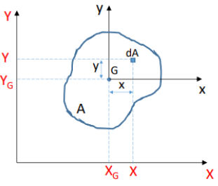
Geometry of Areas
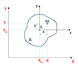
First Moment of Area ( or )
Measure of area distribution relative to an axis.
Centroid ()
The point about which the first moment of area is zero.
Property:
Coordinates:
Centroid of Composite Areas
For complex shapes made of simple geometric parts (e.g., I-beams, T-sections).
Principle: Replace integration with the summation of individual parts.
- : Area of the -th simple shape.
- : Centroid coordinates of the -th simple shape.
Second Moment of Area (Area Moment of Inertia)
Measures the distribution of area relative to an axis (resistance to bending).
Definitions:
Terminology
If computed about the centroidal axes ( passing through ), they are called Central (Centroidal) Moments of Inertia.
Transportation Theorem (Huygens-Steiner)
Relates moments of inertia about centroidal axes to any parallel axes.
Formula:
- : Central (centroidal) moments of inertia.
- : Moments of inertia about the new parallel axes .
- : Coordinates of the centroid in the new system.
- : Total Area.
TIP
The moment of inertia is always minimum about the centroidal axis. Moving the axis away always increases the inertia by .
Principal Moments of Inertia
The specific rotation of axes for which the Centrifugal Moment (Product of Inertia) vanishes ().
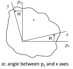
- Principal Axes (): The axes about which is Maximum () and Minimum ().
- Property: These axes are always orthogonal (90° apart). Symmetry axes are always principal axes.
Formulas for Principal Moments: Given in an arbitrary system, the principal values are:
Orientation of Principal Axes
The angle required to rotate the axes to the principal orientation.
Determining the Quadrant
The value of depends on the signs of the numerator and denominator:
- If and
- If and
Mohr’s Circle for Inertia
We can use Mohr’s Circle to represent the variation of moments of inertia with respect to axis rotation.
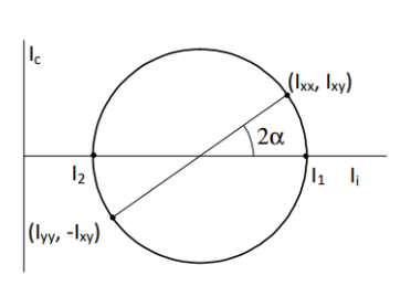
- Centre:
- Radius:
Symmetry and Principal Axes
The Symmetry Shortcut
If a cross-section has an axis of symmetry, that axis is always a Principal Axis of Inertia.
- The Product of Inertia is zero with respect to symmetry axes.
Properties of Common Cross-Sections
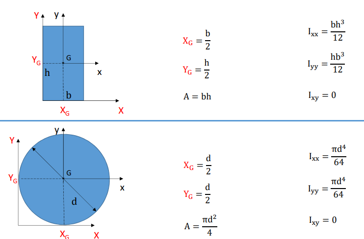
| Shape | Area () | Centroid () | Inertia () | Inertia () | |
|---|---|---|---|---|---|
| Rectangle | |||||
| Circle |
Calculation Table for Composite Areas
| # | ||||||||
|---|---|---|---|---|---|---|---|---|
| 1 | ||||||||
| 2 | ||||||||
| … | ||||||||
Axial Force and Normal Stress
The Kinematic Assumption
Consider a beam subjected only to axial elongation.
- Hypothesis: Cross-sections remain plane and parallel to each other. They move axially () but do not rotate.
- Consequence: The elongation is uniform over the cross-section.
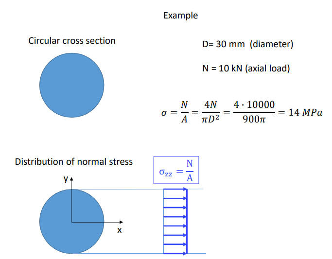
Stress Distribution
Since the strain is constant (), the material law (Hooke’s Law) implies the stress is also constant.
Integrating this constant stress over the area yields the fundamental formula:
- : Internal Normal Force.
- : Area of the cross-section.
The Centroid Condition
IMPORTANT
The above formula is only valid if the external force is applied at the Centroid () of the cross-section.
Proof: If is constant, the bending moments generated are:
For and to be zero (pure axial force), the static moments and must be zero. This is only true if the origin is the Centroid.
Eccentric Loads
If the load is applied away from the centroid (eccentricity), it generates Bending Moments () and you cannot use alone. You must add the bending stress terms.
Example Calculation
12.6 Flexural Behaviour (Bending)
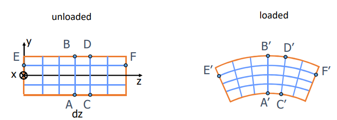
Kinematic Assumptions (Bernoulli-Navier)
Consider a beam subjected to Bending Moments ().
- Hypothesis: Cross-sections remain plane and perpendicular to the deformed longitudinal axis.
- Consequence: The strain varies linearly over the cross-section.
The Navier Formulas (Stress Distribution)
Assuming the coordinate system is Centroidal (origin at ) and Principal (), the relationship between moment and stress is linear.
1. Bending about X-axis ():
2. Bending about Y-axis ():
The Neutral Axis
The axis where the normal stress is zero ().
- In pure bending, the neutral axis passes through the Centroid.
- It divides the section into a region of Tension () and Compression ().
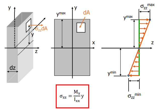
The maximum stress occurs at the point furthest from the neutral axis ().
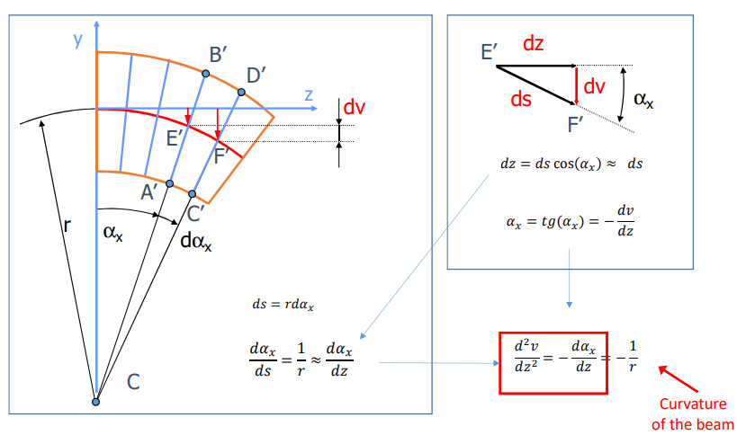
The Elastic Line (Beam Deflection)
We relate the internal bending moment to the physical deformation (curvature) of the beam.
Differential Equation of the Elastic Line
For small deformations, the curvature . The fundamental equation governing beam deflection is:
- : Vertical displacement (deflection) of the beam.
- : Flexural Stiffness (resistance to bending).
- : Bending moment function along the beam axis .
Solving for Deflection (Integration Method)
To find the deformed shape , you must integrate the moment equation twice.
- Integrate once (Slope/Rotation ):
- Integrate twice (Deflection ):
Boundary Conditions: The constants and are determined by the constraints (supports):
- Clamp/Fixed Support: .
- Hinge/Pin Support: .
- Symmetry: At a plane of symmetry, the rotation is zero ().
Exploit Symmetry
If the beam geometry and loading are symmetrical, you only need to solve half the beam. Set the rotation to zero at the symmetry point: . This simplifies the algebra significantly.
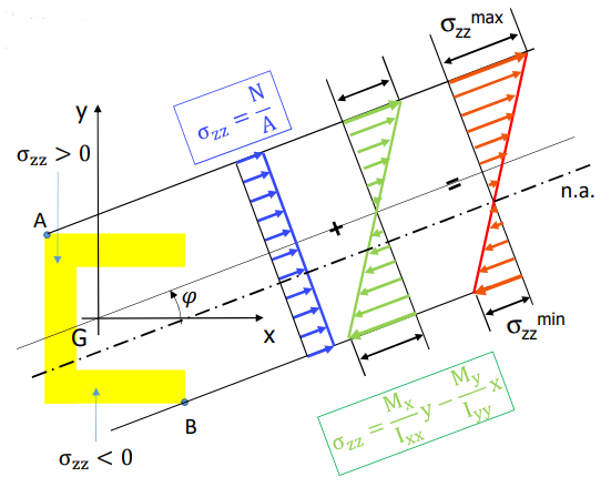
Skew Bending (Bending about a Non-Principal Axis)
When the total bending moment vector is not parallel to one of the principal axes (), it must be decomposed into its components.
Stress Calculation (Superposition)
Due to linearity, we sum the effects of bending about and simultaneously.
- : Components of the bending moment (, ).
- : Principal moments of inertia.
- : Coordinates of the point where stress is calculated.
The Neutral Axis (n.a.)
The line where normal stress is zero ().
Orientation: The angle of the neutral axis () is not usually perpendicular to the moment vector (). It depends on the ratio of stiffnesses.
Physical Meaning
Because beams are often stiffer in one direction than the other (), the beam tends to bend “towards” the weaker axis, causing the neutral axis to rotate away from the moment vector.
Graphical Procedure for Stress Distribution
To draw the stress diagram correctly:
- Find the Neutral Axis: Calculate and draw the n.a. passing through the centroid .
- Identify Critical Points: Find the points on the cross-section furthest from the n.a. (usually corners and ). These are the locations of and .
- Draw Perpendiculars: Project these points onto a line perpendicular to the n.a.
- Plot Stress: Draw the linear variation from maximum tension to maximum compression.
 ---
---
When a beam carries both an Axial Force () and Bending Moments (), the total normal stress is the algebraic sum of the individual effects.
The General Formula (Navier)
The Shifted Neutral Axis
Unlike in pure bending, the Neutral Axis () () does not pass through the centroid when an axial force is present.
- If is tension (), the n.a. shifts away from the tension side.
- If is compression (), the n.a. shifts away from the compression side.
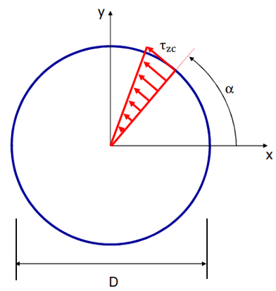
Torsional Behaviour (Circular Sections)
Applies strictly to Circular (solid or hollow) cross-sections.
- Note: For non-circular sections (e.g., rectangles, I-beams), the cross-section warps (does not remain flat), and these formulas do not apply.
Kinematic Assumptions
- Rigid Rotation: Cross-sections remain plane and circular. They rotate rigidly by an angle around the z-axis.
- Straight Radii: Diameters remain straight lines.
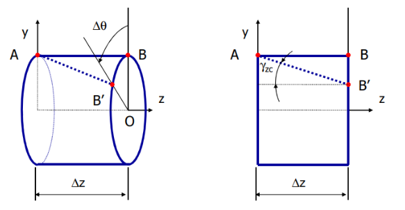
Strain and Stress Distribution
The shear strain varies linearly with the distance from the centre.
Applying Hooke’s Law (), the shear stress is also linear:
The Torsion Formula
Relating the internal Torque () to the twist and stress.
Angle of Twist (Stiffness):
Shear Stress Distribution:
- : Applied Torque.
- : Shear Modulus of the material.
- : Radial distance from centre ().
- : Polar Moment of Inertia.
Polar Moment of Inertia ()
The geometric resistance to torsion. For circular sections, .
| Section Type | Formula for | Diagram |
|---|---|---|
| Solid Circle |  | |
| Hollow Circle |  |
Maximum Stress
The maximum stress always occurs at the outer surface ().
Torsion of Thin-Walled Open Sections
When the cross-section is not circular (e.g., a rectangle or an I-beam), the cross-section warps (bulges in the z-direction), and the simple formulas no longer apply.
Single Rectangular Section For a rectangle of width and thickness (where ):
- Maximum Shear Stress: Occurs at the middle of the long edge.
- Angle of Twist:
Coefficients and
These depend on the ratio .
- For thin sections (), (or 0.333).
Composite Open Sections (L, T, I shapes) We approximate complex open shapes as a collection of individual rectangles.
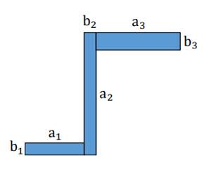
- Equivalent Stiffness (): Sum the stiffness of individual rectangles.
*(Note: This assumes thin walls where $C_2 \approx 1/3$)*
2. Angle of Twist: The entire section rotates together.
- Max Shear Stress: The stress is highest in the thickest part of the section ().
Torsion of Thin-Walled Closed Sections (Bredt’s Theory)
For hollow, thin-walled sections (like tubes or box beams), the shear stress flows around the perimeter. We assume the stress is constant across the thickness and tangent to the midline.
Key Concepts:
- Shear Flow (): The product of stress and thickness is constant along the entire perimeter.
- Enclosed Area (): The area enclosed by the midline of the wall thickness (this is distinct from the material area).
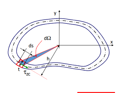
Bredt’s Formula (Stress): Relates the torque to the shear stress and the enclosed area.
Critical Point (Design)
Since the shear flow is constant, the Maximum Shear Stress occurs at the point where the wall thickness is minimum.
Accuracy: Bredt’s formula is an approximation. As the wall gets thinner (), the result converges to the exact theoretical solution.
Stress State and Failure in Torsion
Torsion generates a state of Pure Shear on the cross-section.
A. The Stress Tensor & Mohr’s Circle The only non-zero components are shear stresses.
- Center:
- Radius:
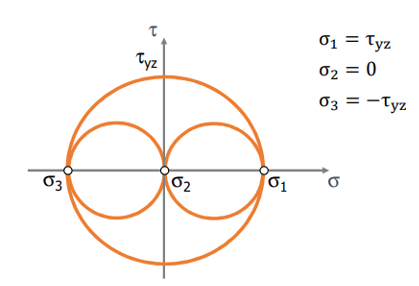
B. Principal Stresses By rotating the element 45°, we find the principal stresses (max tension/compression):
C. Static Failure Criteria How we calculate the “Ideal Stress” () to check against the material’s yield strength ():
| Material Type | Theory | Ideal Stress Formula | Failure Mode |
|---|---|---|---|
| Brittle | Max Normal Stress (Rankine) | Fails in tension at (helical fracture) | |
| Ductile | Max Shear Stress (Tresca) | Fails in shear on the cross-section plane |
Shear Forces in Beams (Jourawsky)
When a beam carries a Shear Force ( or ), it generates a distribution of shear stresses across the section.
- Origin: Shear force is the derivative of the bending moment (). Because changes along , the normal stresses change, creating a “imbalance” that must be equilibrated by shear stress.
Jourawsky’s Formula (The General Law)
Calculates the average shear stress across a chord of width .
- : Shear force acting on the section.
- : Second moment of area of the entire section.
- : Width of the cross-section at the point of analysis (the “cut” width).
- (The Tricky Part): The First Moment of Area of the portion of the area above (or below) the cut.
Common Cross-Sections (Reference)
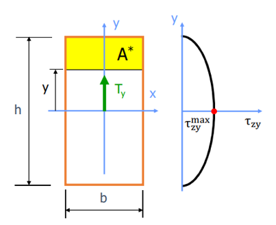
A. Rectangular Section The distribution is Parabolic.
- Maximum stress occurs at the Neutral Axis ().
- Formula:
B. Circular Section The distribution is Parabolic.
- Maximum stress occurs at the Neutral Axis.
- Formula:
Comparison
In long, slender beams, the shear stress is usually negligible compared to the bending stress ..
Thin-Walled Sections (C-Shapes, I-Beams)
For thin sections, the shear stress flows along the walls of the profile.
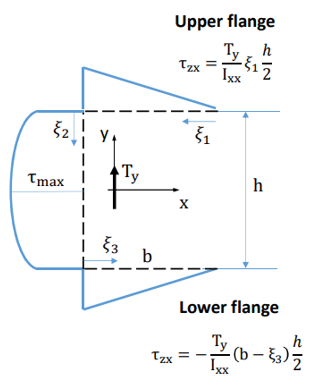
Analysis of a C-Section:
- Flanges (Horizontal parts): Shear stress varies Linearly.
- It is zero at the free ends and maximum at the corner.
- Formula: (where is distance from tip).
- Web (Vertical part): Shear stress varies Parabolically.
- It starts from the value at the corner and peaks at the Neutral Axis.
- Formula: .
Shear Center
SUMMARY
The Problem: If a transverse shear force () is applied at the Centroid () of a cross-section that is not doubly symmetric (like a C-channel), it generates an unbalanced internal twisting moment. The beam will bend and twist.
The Solution: The Shear Center ( or ) is the specific point in the cross-section plane where the shear force must be applied to produce pure bending (zero twist).
Analysis of a C-Section
- Shear Flow Imbalance: The shear force generates shear stresses in the web () and horizontal stresses in the flanges ().
- Internal Torque: The forces in the flanges () are equal and opposite, creating a couple (torque) that tries to twist the section.
Determining the Position ()
To find the location of the shear center (distance from the centroid ), we enforce equilibrium: the moment generated by the external force must equal the moment generated by the internal shear flow.
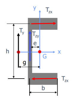
Moment Balance Equation (about G):
- : Resultant shear force in the flange.
- : Distance between flange centerlines.
- : Distance from web centerline to Centroid .
Effect of Misalignment
If the external load is applied at the Centroid (and not the Shear Center), the system is statically equivalent to a Shear Force plus a Twisting Moment.
This causes combined bending and torsion failures.
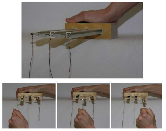
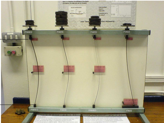
Visual Proof
The image below demonstrates the difference. The beams loaded at the centroid (left) twist significantly. The beam loaded at the shear center (right) bends straight.
Ideal Stresses (Failure Criteria)
In a generic point of the beam, we simultaneously have Normal Stresses () and Shear Stresses (). To check for failure, we must combine these into an equivalent “Ideal Stress”.
The Stress State
The total shear stress at a point is the vector sum of its components:
The Principal Stresses () for this state are:
Failure Hypotheses
Depending on the material (Brittle vs. Ductile), we use different formulas to calculate .
A. Rankine (Brittle Materials) Based on the Maximum Normal Stress.
B. Tresca (Ductile Materials) Based on the Maximum Shear Stress. Conservative and safe.
C. Von Mises (Ductile Materials - Most Common) Based on Distortion Energy. This is the standard for metals like steel.
The "Safety Check"
Once you calculate , the safety condition is simply:
Buckling of Slender Beams (Euler Instability)
The Phenomenon: Slender beams subjected to an axial compressive load () do not fail by crushing; they fail by sudden bending (buckling) sideways.
The Governing Equation
Unlike standard beam theory, here the internal bending moment depends on the deformation itself ().
- Equilibrium: .
- Differential Equation:
Euler’s Critical Load ()
The load at which the beam becomes unstable and buckles. It always happens about the weakest axis ().
- : Young’s Modulus.
- : Minimum Moment of Inertia of the section.
- : Effective Length of the column.
Effect of Boundary Conditions ()
The effective length depends on how the beam is supported.
| Supports | Effective Length () | Critical Load Capacity |
|---|---|---|
| Pinned - Pinned | ||
| Fixed - Free (Cantilever) | (Weakest) | |
| Fixed - Fixed | (Strongest) | |
| Fixed - Pinned |
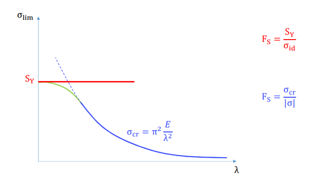
Critical Stress and Slenderness
We define the Slenderness Ratio () to determine if a beam will yield or buckle.
Critical Stress:
Failure Modes
- Short / Squat Beams (Low ): Fail by Yielding ().
- Long / Slender Beams (High ): Fail by Buckling ().
You must check which curve controls the design.