Self-inductance describes how much of an inductor’s (solenoid) current creates flux through itself.
The unit is (Henry).
Mutual inductance describes how much of one loop’s current creates flux though another.
(Form ).
Total flux is:
Tor recall, in solenoids:
Therefore
Where , being .
Flux per unit length:
To find inductance per unit length:
Inductors
definition.
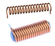
A solenoid is a sequence of loops with current flowing through them. An inductor is simply a solenoid in a circuit.
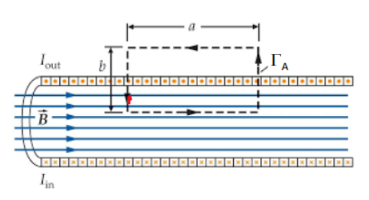
Application of Ampere's Law
We use the Amperian Loop below:
To get:
If we have self-inductance in a circuit:
In an inductor:
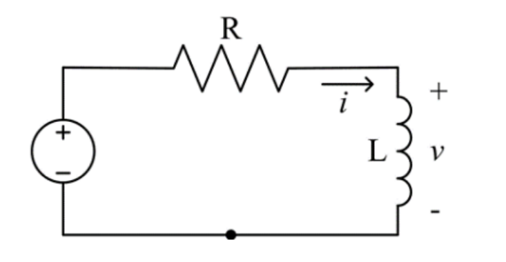
An RL circuit
Inductors resist a change in current.
How do vary over time?
Where is the volume.
Transformers
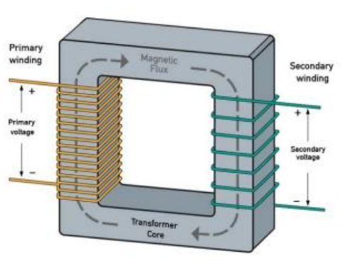
Warning
NO POWER IS CREATED! If voltage increases, current decreases!
Warning
Transformers ONLY work with AC current.
Common Circuits
RC Circuits
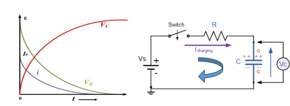
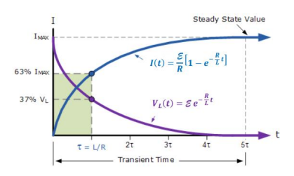
When the switch is closed we get the following time-dependant properties:
Inductor and AC Generator
We have:
HOWEVER, current has a phase delay with respect to voltage.
Inductive Reactance
, measured in . Zero when DC current is present.
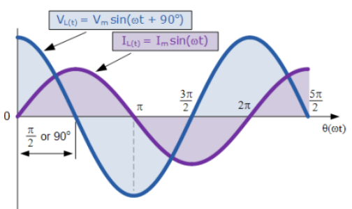
We can deduct that inductors block high-frequency signals.
Capacitor and AC Circuit
This time, current is ahead of voltage.
Capacitive Reactance
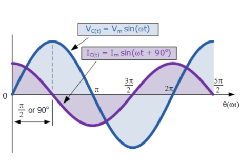
Capacitors block low frequency signals.
RLC Circuits
Resistor + Capacitor + Inductor
The Setup: Free RLC (No Generator)
When there is no external power source, the energy just sloshes back and forth between the inductor and capacitor while the resistor burns it off as heat.
Governing Equation
The differential equation for the current is a damped harmonic oscillator:
The Three Destinies (Damping)
Depending on the resistance , the circuit behaves in one of three ways:
- Overdamped (): The current lazily decays to zero. No oscillations. It’s like moving through molasses.
- Underdamped (): The system vibrates! The current oscillates back and forth, slowly dying out. This happens at the resonant frequency .
- Critically Damped (): The perfect balance. The current returns to zero as fast as physically possible without overshooting.
The Driven RLC (With Generator)
Now we attach a generator with frequency . The circuit fights back with Impedance ().
Impedance ( )
Think of this as “AC Resistance.” It has a real part (Resistor) and an imaginary part (Reactance from and ).
(Inductor hates fast changes)
(Capacitor hates slow changes)
Resonance
Resonance happens when the Inductor and Capacitor perfectly cancel each other out ().
At Resonance ( )
Impedance is minimized: (Pure resistance).
Current is maximized: The circuit accepts maximum power.
Phase: Voltage and Current are perfectly in sync ().
Frequency:
Frequency Behaviour
If you are not at resonance, one component dominates the other:
| Frequency | Dominant | Type | Phase |
|---|---|---|---|
| Low () | Capacitor () | Capacitive | Voltage lags Current |
| Resonance () | Resistor | Resistive | In Phase |
| High () | Inductor () | Inductive | Voltage leads Current |
The Q-Factor
The Quality Factor () tells you how “sharp” the resonance peak is.
- High Q (Low R): A very sharp, narrow peak. The circuit is very selective.
- Low Q (High R): A flat, wide hill. The damping is heavy.
Power
Finally, how much energy are we actually using?
Power Factor
You cannot just multiply max voltage and max current. You must account for the phase difference () and use RMS (Root Mean Square) values.
If the phase difference is (), power is zero. The capacitor/inductor just store and release energy without burning it.