Hardening by Carburizing
The primary goal here is to achieve a surface that is hard and wear-resistant while maintaining a tough, ductile core to absorb shock.
The Mechanism This process exploits specific metallurgical factors:
- Martensite hardness increases as the carbon percentage increases.
- Martensite forms from austenite upon quenching.
- Carbon is highly soluble in austenite.
- The diffusion/absorption rate increases significantly with temperature.
Process Parameters
- Temperature (): .
- Time: hours.
- Applicable Materials: Plain carbon steels () and low carbon low alloy steels.
Applications Used for components requiring durability under load, such as gears, shafts, bearings, and piston rods.
Outcome
- A carbon concentration profile develops along the thickness, achieving maximum Vickers Hardness (HV) on the surface.
- The austenite transforms into martensite via oil quenching.
Hardening by Nitriding
Unlike carburizing, this process aims for an extremely hard surface while retaining a tough core.
The Mechanism
- Nitrogen forms very hard compounds (nitrides) with Iron.
- Nitrogen solubility in ferrite is very low.
- At ferrite stability temperatures, diffusion is slow, and the formation of nitrides inhibits further Nitrogen diffusion.
Process Parameters
- Temperature (): .
- Time: Approx. 70 hours (can range 40-100h).
- Chemical Reaction: Ammonia dissociates: . Atomic Nitrogen then dissolves into the steel.
Applicable Materials
- Nitriding steels: Plain medium carbon steel () and medium carbon low alloy steels (tempered/semi-finished).
- Common alloying elements: Al, Cr, V, Mo.
Structure of the Nitrided Layer
- Outer Layer: .
- Inner Layer: .
- Depth: A thin layer, typically mm.
- Hardness: Very high superficial hardness ( HV).
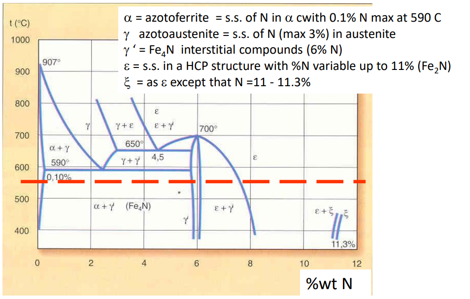
The Fe-N Metastable Phase Diagram
Nitriding Steel Compositions Specific alloys are required for optimal nitriding results.
| Steel Type | %C | %Si | %Mn | %Cr | %Mo | %Al | Hardness after Nitriding |
|---|---|---|---|---|---|---|---|
| 30 Cr Mo 10 | 0.30 | 0.35 | 0.60 | 2.50 | 0.40 | - | 650 HV |
| 38 Cr Al Mo 7 | 0.38 | 0.30 | 0.60 | 1.70 | 0.25 | 1.0 | 1050 HV |
| 42 Cr Al Mo 7 | 0.42 | 0.35 | 0.55 | 1.70 | 0.35 | 0.40 | 900 HV |
Comparison: Nitriding Steels vs. Carburizing
Performance Comparison
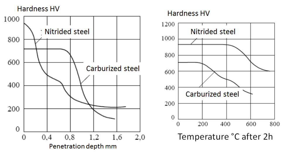
- Nitrided Steel: Achieves higher surface hardness (up to 1000-1200 HV) but the depth of penetration is shallow ( mm).
- Carburized Steel: Lower peak surface hardness ( HV) but maintains hardness to a greater depth ( mm).
Harris’ Formula for Penetration Depth To calculate the depth of the treatment: Where is temperature in Kelvin and is time in hours.
Post-Treatment Processing
| Process Step | Carburized Parts | Nitrided Parts |
|---|---|---|
| Pre-treatment | Normalizing + work hardening annealing | Normalizing + Work hardening annealing |
| Machining | Roughing (medium thickness) | Roughing (medium thickness) |
| Main Process | Carburizing | Tempering |
| Hardening | Quenching + tempering at | Finish Nitriding |
| Finishing | Finish by grinding | Finish by grinding |
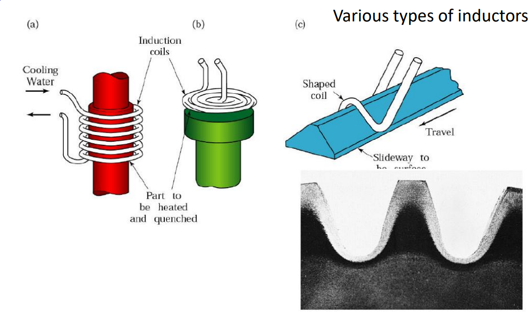
Induction Hardening
Definition
The process uses alternating current to generate a magnetic field, which creates induced currents in the workpiece. This results in localized thermal energy.
Current Penetration Depth () The depth of heating is controlled by the frequency:
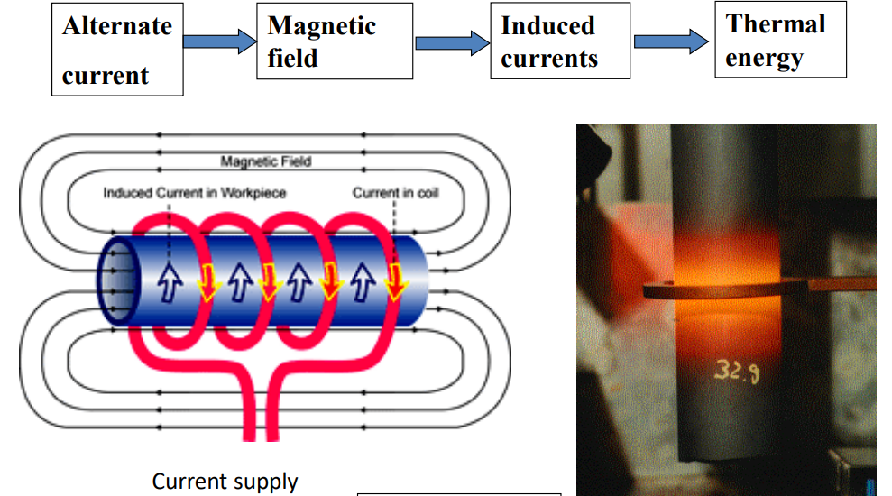
Inductor Types Various shapes exists for different geometries:
- Single-shot coils for cylindrical parts.
- Shaped coils for slideways or gears.
Slideways vs Coils
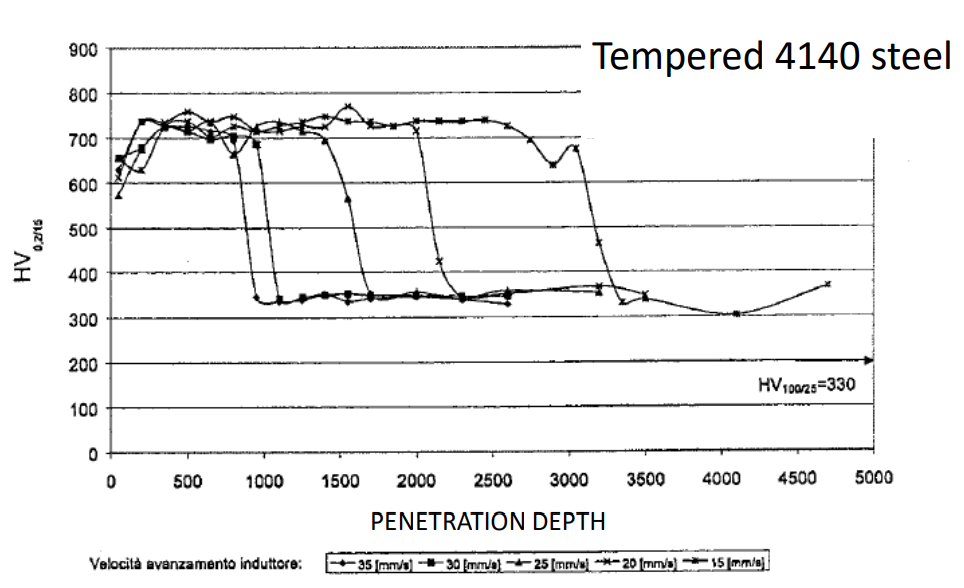
Hardness Profiles Induction hardening creates a sharp transition in hardness. For example, in Tempered 4140 steel, hardness holds steady around 700 HV before dropping sharply to the core hardness ( HV) at a specific depth determined by the induction frequency and speed.
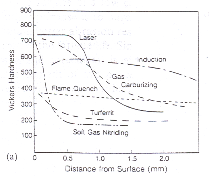
Heat vs. Chemical Surface Treatments Overview
All surface heat treatments generally confer a compressive stress state on the surface, which increases fatigue resistance.
Process Comparison Table
| Process | Steel Type | Component | Conditions |
|---|---|---|---|
| Induction (3 kHz) | 0.38% C | Axle | Water Quenched, Tempered at |
| Flame Hardening | 0.67% C | Wheel | Water Quenched, Tempered at |
| Carburizing | 0.2% C (Ni-Cr-Mo alloy) | Gear | Oil Quenched, Tempered at |
| Laser (15 kW) | 0.43% C (Mn alloy) | Gear | Self Quenched |
| Nitriding | 0.2% C (Cr-V-Al alloy) | Gear | Process carried out at |
Residual Stress Profiles
- Nitriding (Turferrit/Soft Gas): Creates the highest compressive residual stress ( to MPa) right at the surface.
- Induction: Creates deep compressive stress, but lower magnitude at the surface compared to nitriding.
- Laser: High surface hardness but shallower stress profile.
Weldability and Heat Affected Zone (HAZ)
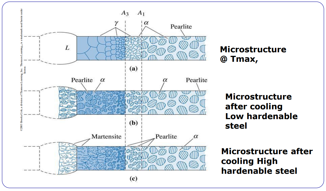
When welding steels, the thermal cycle alters the microstructure adjacent to the weld. This is the Heat Affected Zone (HAZ).
Structure of the Welding Zone
- Solidified Weld: The melt zone.
- Grain Growth Zone: Liquid + (austenite) transition.
- Recrystallized Zone: region.
- Partially Transformed Zone: .
- Tempered Zone: Below temperature.
- Unaffected Base Material: Original microstructure.
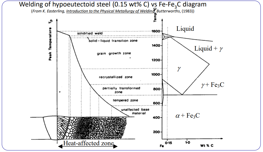
Microstructural Evolution The final structure depends heavily on the hardenability of the steel.
- At : The structure becomes Austenite () near the melt line.
- Cooling (Low Hardenable Steel): Reverts to Pearlite and Ferrite ().
- Cooling (High Hardenable Steel): Forms Martensite, which is brittle and prone to cracking.
Weldability Criteria
- To be weldable, steel must have low hardenability (low alloying elements).
- Steels up to are weldable, but caution is needed for higher carbon contents.
- Risk: Cracks can form underneath the welding bead in the HAZ.
Summary Tables
Chemical Surface Treatments Summary
| Process | Compound | Temp () | Time (h) | Thickness () | Hardness (HV) | Distortion |
|---|---|---|---|---|---|---|
| Nitriding | Fe-N | 500-550 | 1-70 | 50-100 | 700-1000 | Min |
| Nitro-carb. | Fe-(C,N) | 550-650 | 1-6 | 50-200 | 700-1000 | Min |
| Boriding | Fe-B | 600-1000 | 1-4 | 50-500 | 1000-1800 | High |
| Carburizing | Fe-C | 700-1050 | 1-46 | 100-7000 | 750-950 | High |
| Process QUAD | CrCN, VCN, TiCN | 400-700 | 1-8 | 5-20 | 1200-2500 | Min |
Wear Resistant Ceramic Coatings
| Process | Surface Layer | Method | Surface T () | Thickness () | Hardness (HV) | Distortion |
|---|---|---|---|---|---|---|
| Cr hard | Cr | Electrolysis | 50-80 | 20-50 | 700-800 | Low |
| Thermal CVD | TiC, TiCN, TiN | Gas | 800-1100 | 3-15 | 1500-2000 | High |
| Plasma CVD | TiC, TiN | Arc in vacuum | 300-600 | 1-6 | 1500-2000 | Low |
| PVD | TiN, CrN | N in vacuum | 300-600 | 1-6 | 2000-4000 | Low |
| Flame coating | Ni, Cr, B, Si | Powder melting | 1000-1100 | 500-2000 | 600-800 | High |
| Stellite | Ni, Cr, B, Si | Melting (arc) | 2000-5000 | 300-900 | High |